This is especially true when you consider that many machined parts. Structural steel and sheet metal are the usual starting materials for fabrication along with the welding wire flux.

Cast Iron Product Drawing And Renderings Help Facilitate The Iron Casting Purchasing Process
Prepare a technical drawing in 7 steps.

. Casting and Machining are Complementary processes to each other in investment casting. Dimension of a raw casting before machining see figure I the necessary ma- chining allowance being included see figure 2. Figure 1 - Drawing indications see clause 4 1 Licensed to ASSOC.
Tmoose Mechanical 27 Jan 12 1245. Assembling joining of the pieces is done by welding binding with adhesives riveting threaded fasteners or even yet more bending in the form of a crimped seam. Im in the midst of dealing with such an issue from the other end.
Ideal Applications for Machining and Molding. Machining sensitiviy analysis for both options change in total income had the most effect 20 change in income resulted in 30 change in present value highlow for casting electricity was significant as well larger amount higher significance salvage least signigficant sensitivity analysis conclusion we chose the machining process equipment cost. The casting process is an essential part of metalworking.
Forging Drawing vs Machining Drawing. For the part features or details the die can be made with all surface details included to produce parts directly saves time greatly. We name the file Part 7 machining and push the Save button.
Figure G4 Part 7 Casting File We select the Inventor icon in the upper left corner of the Inventor 2012 window. Sometimes castings can be utilized in the exact form that they leave the mold. Forging is the application of thermal and mechanical energy to steel billets or ingots to cause the material to change shape while in a solid state.
Ideal Applications for Machining and Molding. So if you are casting rather than machining then you use only use the material needed. This is a government job and the technical data package allows the option of making the part from the forging or 17-4PH bar stock.
The next layer of powder is placed and the process repeats itself. The process is fast and repeatable. Any post-casting machining will be only to add in tightly toleranced features or other finishing details.
Die casting is a near-net-shape process. From the amount of production CNC machining is more ideal for low volume products because no tooling cost is required. To summarize machining is ideally used for prototyping small quantity runs precision tolerances and components with large complex volumes.
The metal 3D printer spreads a thin layer of the metal powder on the bed then a laser melts the metal creating the shape of your 3D model. In many circumstances though the increase in production and the robustness of todays moulds can mean that the cost of tooling can soon be recovered. For sure the cast will not naturally have a very smooth surface finish so some work will be needed to make it look nice - whether thats a layer of filler and paint or some sort of sandingsmoothing of the.
In some eras and in some industries the foundry was given the drawing of the finished part and they create a drawing of what the finished casting should look like and of course the pattern needed to create the cast part. Die-cast tooling is often regarded as the biggest cost and consequently the biggest drawback of the die-casting process. Difference between casting vs forging.
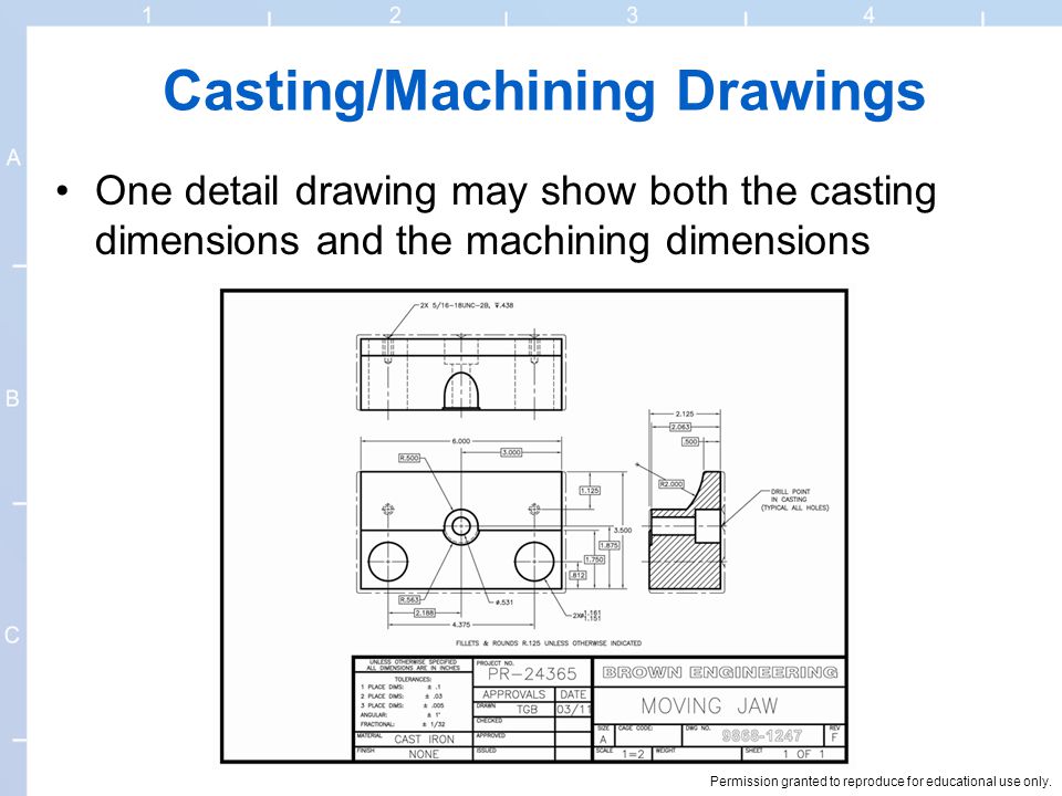
Casting is the process where metal is heated until molten. Figure G4 Part 7 Casting File We select the Inventor icon in the upper left corner of the Inventor 2012 window and we select Save As from the drop down menu. The finish machine drawing only shows dimensions for a few features that get machined such as bores.
We see our casting drawing and we will save the file as Part 7 machining. This process holds the ability to create a variety of complex parts in a wide selection of metals for countless industries. Define the most important views and place the relevant orthographic in the center of the drawing leaving enough space between them to add dimensions.
A shop cast a set of parts I designed. They often however need to be machined in order for the part to be further perfected. Selective Laser Melting SLM is an Additive Manufacturing technology that uses metal powder to create your parts.
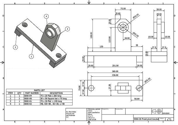
This technical drawing shows the machine parts assembly using joining by threaded fasteners. This will take a fraction of the time of machining a billet from solid. --- Raw casting basic dimension 1.
Forging is the application of thermal. Here is a summary of the steps you should follow when drafting your technical drawing. While in the molten or liquid state it is poured into a mold or vessel to create a desired shape.
On the other hand having a casting with a 50mm 2 hole from the casting when you need a 52mm 2 116 hole is much less effort than machining the hole from a solid lump. Cast molding is great for large quantity runs exactness from lot to lot and parts where a skin or detailed texture is important. Die casting is the first considered option for a high volume of consistent parts.
The Single Source Advantage. Figure G5 Part 7 Machining We then can close the Part7 drawing and open the.

Scott Lester Drafting Design Drawings

Solved 2 A Choose An Appropriate Casting Process Chegg Com

The Bearing Bracket Casting Part Drawing Download Scientific Diagram
15 Detail Drawings Permission Granted To Reproduce For Educational Use Only Explain Terms And Standards Related To Various Types Of Drawings Used In Ppt Download

Machinist Drawings Building Codes Northern Architecture
The Casting Process Of The Enclosed Switchgear Outer Body Casting Download Scientific Diagram

Scott Lester Drafting Design Drawings
How To Design Drawing For Investment Casting
0 comments
Post a Comment